4.9
Z
Z
Z
L
W
R
W
R
L
Tensioner Devices
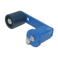
Chain rider set type P
Chain rider type P
Roller chain
ANSI
DIN 8187
Type
Art. No.
W
L
X
Y
Z
Torque
hex nut 0.5 d
[Nm]
Adjusting
range track
R
Size
SE
Weight
[kg]
Simplex “S”
35
40
50
60
ISO 06 B-1
ISO 08 B-1
ISO 10 B-1
ISO 12 B-1
P3/8" – 8 S
P1/2" –10 S
P5/8" –10 S
P3/4" –12 S
06 550 001
06 550 002
06 550 003
06 550 004
M8
M10
M10
M12
45
55
55
80
74
96
126
148
37
48
63
72
10.2
13.9
16.6
19.5
11
20
20
35
19 – 34
23 – 41
24 – 39
30 – 61
11
15 /18
18
27
0.05
0.10
0.12
0.18
Duplex “D”
35
40
50
60
ISO 06 B-2
ISO 08 B-2
ISO 10 B-2
ISO 12 B-2
P3/8" – 8 D
P1/2" –10 D
P5/8" –10 D
P3/4" –12 D
06 560 001
06 560 002
06 560 003
06 560 004
M8
M10
M10
M12
45
55
70
80
74
96
126
148
37
48
63
72
10.2
13.9
16.6
19.5
11
20
20
35
25 – 30
30 – 34
34 – 46
40 – 52
11
15 /18
18
27
0.07
0.12
0.17
0.26
B
A
D
C
Roller chain
ANSI
DIN 8187
Type
Art. No.
A
+0.2
0
B
C
D
Weight
[kg]
35
40
50
60
ISO 06 B
ISO 08 B
ISO 10 B
ISO 12 B
P3/8"
P1/2"
P5/8"
P3/4"
06 540 001
06 540 002
06 540 003
06 540 004
8
10
10
12
10.2
13.9
16.6
19.5
37
48
63
72
74
96
126
148
0.02
0.03
0.05
0.07
Mounting instructions for Chain Drives
See also complementary mounting instructions on page 4.5.
Standard positioning
The ROSTA tensioning device
should be placed on the slack-
side of the chain drive, close
by the smaller sprocket wheel
in order to enlarge its contact-arc, therefore contact applica-
tion from outer side of drive. In mounted position the tension-
er-arm should stay close to parallel to the chain run, in drain
direction. By extremely long chain drives it is recommend-
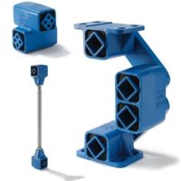
able to install several tensioners or the type “Boomerang
®
”
in order to enlarge the slack compensation.
Reversible chain drive
By reversible chain transmis-
sions it is recommendable to
install a tensioner on each
side of the chain-strands. Due
to the alternate occurring of the slack, both tensioners should
only be pre-tensioned up to max. 20°, in order to retain a re-
set-path of 10°, when strains are changing from slack span on
working span in reversible applications.
Sprocket teeth in mesh
By the initial tensioning of the chain at
least three teeth of the tensioner sprocket
wheel should be in mesh with the rollers.
The min. distance between sprocket
wheel of the tensioner to the next sprocket
wheel in the chain drive should be at least
four chain-pitches.
Adjustment of chain-track
The wheel of the sprocket wheel set is adjust-
able according to the position of the chain
drive track. The wheel is positioned between
two nuts on the threaded shaft. In changing
the adjustment band “R”, the track of the ten-
sioner wheel can be set according to relevant
strand course. After positioning of sprocket,
re-tighten the two nuts on the side. The count-
er-nut “B” remains always tightened.
Chain rider type P
Chain rider set type P
Chain Drives
R
C
B
Y
X
G
l
i
d
e
a
n
g
l
e
o
f
r
i
d
e
r
m
a
x
.
9
0
°
For an ideal positioning of the chain rider/s
on the threaded rod we do recommend to
position them on each side by means of two
nuts, secured against each other, with some
play for swivelling into working position.
Simplex “S”
Duplex “D”


