4.5
Tensioner Devices
Tensioning force F
The tensioning force can be continuously adjusted. The max.
pre-tensioning angle is +
30° out of neutral position. Tensioning
force table for types
SE / SE-G / SE-R / SE-F / SE-I
by using
hole-
position “normal”
for sprocket-, rider- and roller fixation.
General technology
SE-I 40:
same tensioning force like SE 38.
SE-W:
40 % lower tensioning force than standard versions
(Rubmix 40 inserts).
SE-FE:
see page 4.7
When fixing the sprockets, riders and rollers in
arm-position “hard”, tensioning force will increase
on about 25 %.
Quality 8.8
Quality 12.9
for
SE-F / SE-FE
M6
10 Nm
17 Nm
M8
25 Nm
41 Nm
M10
49 Nm
83 Nm
M12
86 Nm
145 Nm
M16
210 Nm
355 Nm
M20
410 Nm
690 Nm
M24
750 Nm
Use of
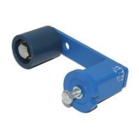
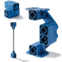
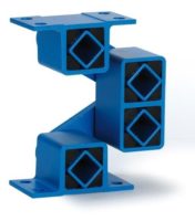
SE-B Boomerang
®
tensioners
In very long chain and belt drives it was
recommendable to install on the slack-side
several tensioners, in order to compensate
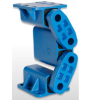
occurring elongation. The “Boomerang”
with its bent double-arm equipped with
two chain sprockets or a combination of
grooved pulley and flat-roller (belt-drives)
offers a triple-compensation of
chain and belt elongations, due to
S-shape contact-arc.
Tensioner mounting
Tighten the flange screw slightly. Grip
the housing with flat-wrench and set
needful pre-tension by rotating the
housing in the required direction. Tight-
en the central screw according the
above mentioned tightening moment
M
A
.
Position flat-wrench close
by the flange-bottom.
Z-configuration of sprockets or riders
If there is the need to install sprockets,
riders or rollers on the outer arm-side of
the tensioner, then the distance “Z”
should be as little as possible to avoid a
misalignment in element parallelism. Fur-
thermore the pre-tension force should not
exceed 50 % of the capacity = max.
pre-tension angle of ~ 20 °.
F
pretension
infinitely variable
in the positions
“normal” or “hard”
torsion angle scale
adjustable
chain track
shock absorption
360 ° position
flexibility
positioning notch
M
A
one bolt central
mounting on
front or base
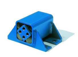
The ROSTA tensioners should be installed on a stiff, even
and clean machine part by means of the central bolt.
The
frictional connection on flange is usually fully suffi cient for
final positioning. The positioning notch on flange can be
used to assure the tensioner additionally on uneven and
dirty surfaces by setting a roller-pin.
Tightening moment M
A
for attachment screw
Table mentioning the tightening moment for the
central screw (included in scope of delivery).
Mounting instructions
For further mounting instructions please consult the pages 4.9 – 4.11.
Z
F
Size SE
Pre-tension
10°
F [N]
s [mm]
Pre-tension
20°
F [N]
s [mm]
Pre-tension
30°
F [N]
s [mm]
11
15
14
40
27
80
40
15
25
17
65
34
135
50
18
75
17
185
34
350
50
27
150
23
380
44
810
65
38
280
30
720
60
1500
88
45
520
39
1350
77
2650
113
50
740
43
2150
86
4200
125


