2.39
Oscillating Mountings
Installation guidelines for AV mountings
1
With the right-hand and left-hand threaded connection in the AV housing the
length X of the suspension rod can easily be adjusted, this length has to be iden-
tical for all four suspension rods.
The indicated angular oscillating lim-
itations have to be respected!
2
Only the
crosswise
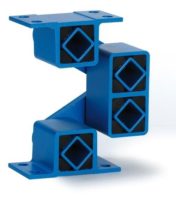
(90° offset) installation of the two AV elements per suspen-
sion rod is guaranteeing for a harmonic and circular motion of the screen-box.
3
The crosswise installation of the AV elements has to be identical on all four suspen-
sion rods, e.g. all upper AV mounts shall stay 90° offset. (For the suspension or
support of the discharge-ends of “ROTEX” sifter types the two elements per rod
shall stay parallel to each other.)
4
To avoid unwanted tilting motions or screen-box distortions (by standstill) we do
recommend the installation of the lower AV-brackets on the level of the center of
gravity “S” of the screen-box.
5
Please consult ROSTA by the selection of AV elements for staying, free oscillating
gyratory sifters.
β
≤
± 2°
X
β
≤
± 2°
β
≤
± 2°
α
≤
± 5°
1
Calculation Example
Description
Symbol
Example Unit
Calculation formula
Total oscillating mass (material included)
m
800 kg
Angle of oscillation
Eccentric radius
2
R
20 mm
Length of suspension rod
X
600 mm
Angle of oscillation (out of R and X), shall not exceed
±
2 °
2
β
+
1.9 °
Revolutions
n
s
230 min
–1
Quantity of suspension rods
z
4 pcs.
Load per suspension rod
Load per suspension rod
G
1962 N
Max. load capacity per rod with AV 27 mountings
G
max
3000 N
Element Selection:
4 pcs. AV 27 and 4 pcs. AV 27 L
(left-hand threaded), the two AV elements per suspension rod have to be installed
crosswise (90° offset).
β
=
arctan
[°]
R
X
G =
[N]
m · g
z
2
circular oscillation
3
elliptical oscillation
X
4
1


