2.30
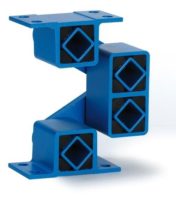
Oscillating Mountings
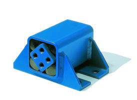
Spring Accumulators
Type DO-A
A
B
B
S
E
F
L
L1
I
A
G
H
D
Further basic information and calculations on pages 2.22–2.24.
Art. No.
Type
c
s
[N/mm]
A
B
+ 0.5
D
E
F
ø I
S
G
H
L
L1
– 0.3
Weight
[kg]
Material structure
01 041 013
DO-A 45 x 80
100
12
+ 0.5
35
85
73
150
–
45
–
–
80
90
1.9
Light metal profile,
ROSTA blue painted
Light metal profile,
nodular cast iron,
ROSTA blue painted
01 041 014
DO-A 45 x 100
125
–
–
100
110
2.3
01 041 016
DO-A 50 x 120
190
M12
40
ca. 89
78
ca. 168
12.25
50
30
60
120
130
5.5
01 041 019
DO-A 50 x 160
255
30
60
160
170
7.4
01 041 017
DO-A 50 x 200
320
40
70
200
210
8.5
Angle of oscillation DO-A
(series connection)
Accumulator cons. of
2 x DO-A 45
Accumulator cons. of
2 x DO-A 50
R
sw
max. n
s
max. K
R
sw
max. ns
max. K
+
6°
15.3
30.6
360
2.2
16.4
32.8
340
2.1
+
5°
12.8
25.6
500
3.6
13.6
27.2
470
3.4
+
4°
10.2
20.4
740
6.2
10.9
21.8
700
6.0
0
0
c
s
= dynamic spring value of the complete accumulator by oscillating angle of + 5° and revolutions n
s
between 300–600 min
-1
1 spring accumulator is always consisting of 2 pcs. DO-A elements!
Installation guidelines
The connection structures (forks) between the
ROSTA DO-A elements have to be provided by
the customer. The two side plates have to stay
right-angled
(90°) in regard to the DO-A el-
ement axis. It is recommendable to weld a cross
bracing (V) between the side plates.
The two DO-A elements of the accumulator
have to stay
parallel
to each other and also
parallel
to the rocker arms of the trough. Their
fixation on trough and base frame shall be
made by means of a stiff fork structure. The fix-
ation of the DO-A elements (on inner element
section) shall be made with shoulder studs.
Operating parameters


