2.29
Oscillating Mountings
F
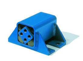
Drive Heads
Type ST
Installation guidelines
For the installation of the drive heads type ST under the trough-bottom it requires a
stiff structure, ideally a heavy and rather long frame construction surrounding the
power input from the eccentric drive. Too light and too short mounting structures for
the drive heads could be submitted to early material fatigue and generate cracks on
the feeding trough. The drive heads have to be installed fully free of play (frictional
connection). By multiple power transmission with several drive heads, all driving rods
have to be adjusted on exactly the same length. The force transmission from the ec-
centric drive should stay
right-angled
to the guiding rocker arms. This supports a
smooth course of the shaker.
Art. No.
Type
F
max.
[N]
n
s
[min
–1
]
max.
α
ST
+
5°
A
B
C
D
E
H
J
K
L
M
S
Weight
[kg]
Material
structure
Bolting on
inner square
07 031 001
ST 18
400
600
50
55
0
– 0.3
31.5
45
20
12
+ 0.3
6
22
39
M12
M12-LH
18
0.2
Light metal casting
Light metal profile
Housing ROSTA blue painted
End-to-end
screw or
threaded bar
quality 8.8
07 041 001
ST 18L
07 031 002
ST 27
1’000
560
60
65
0
– 0.3
40.5
60
27
20
+ 0.4
8
28
54
M16
M16-LH
27
0.4
07 041 002
ST 27L
07 031 003
ST 38
2’000
530
80
90
0
– 0.3
53
80
37
25
+ 0.4
10
42
74
M20
M20-LH
38
1.1
07 041 003
ST 38L
07 031 004
ST 45
3’500
500
100 110
0
– 0.3
67
100
44
35
+ 0.5
12
48
89
M24
M24-LH
45
1.8
screw
quality
8.8
07 041 004
ST 45L
07 031 005
ST 50
6’000
470
120 130
0
– 0.3
69.5
105
47
40
+ 0.5
M12 x 40
60
93
M36
M36-LH
50
5.5
Nodular cast iron
07 041 005
ST 50L
07 031 015
ST 50-2
10’000
470
200 210
0
– 0.3
69.5
105
47
40
+ 0.5
M12 x 40
60
93
M36
M36-LH
50
6.9
07 041 015
ST 50-2L
07 031 026
ST 60
13’000
440
200
210
+ 0.2
85
130
59
45
M16
80
117
M42
M42-LH
60
15.6
Steel
ROSTA blue painted
Shoulder studs
quality 8.8 for
optimizing
frictional
connection
07 041 026
ST 60L
07 031 016
ST 60-3
20’000
440
300
310
+ 0.2
85
130
59
45
M16
75
117
M42
M42-LH
60
20.2
07 041 016
ST 60-3L
07 031 027
ST 80
27’000
380
300
310
+ 0.2
100
160
77
60
M20
90
150
M52
M52-LH
80
36.7
07 041 027
ST 80L
+ 0.5
0
Further basic information and calculations on pages 2.22–2.24.
n
s
= max. revolutions by oscillation angle
+
5°; if osc. angle is below, higher rpm’s are applicable, consult “permissible fre-
quencies” in the Technology part of the ROSTA general catalogue.
F
max.
Calculation of the acceleration force F on page 2.22.
Series connection of 4 pcs. ST 50
F
H
J
H
L
S
M
K
C
D
E
A
B
ø
16,5
50
80
J
M
K
C
D
E
A
B
J
H
H
L
S
J
50
ST 60-3: 80
ST 80: 90
ST 60-3:
ø
16,5
ST 80:
ø
20,5
ST 50-2
ST 18 – ST 50
ST 60
ST 60-3 and ST 80
Length of driving rod A
ST
and eccentric radius R
To follow the guidelines of the permissible frequencies the angle of oscillation
α
ST
should not exceed
+
5.7°. This angle is corresponding to the ratio R : A
ST
of 1 : 10.
Calculation of the oscillation angle for ST
Eccentric radius
R
[mm]
Center distance
A
ST
[mm]
Oscillation angle
α
ST
+
[°]
α
ST
=
arcsin
R
A
ST
[°]


