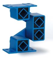
2.24
Oscillating Mountings
m
1
m
2
The 9 installation steps for a two mass system with double rocker arms:
1. All fixation holes for the rockers in trough, counter-mass and machine frame have to be
drilled very accurately previous the final machine assembling.
2.
Installation of the middle elements of the rocker arms on the central machine frame, all inclina-
tion angles duly adjusted (e.g. 30°), tightening of the screws with required fastening torque.
3.
Lifting of the counter-mass with accurate horizontal alignment until the bores in the counter-mass
frame stay congruent with the bore holes of the lower element. Jamming of the counter-mass
with e.g. wooden chocks.
4. Tightening of the fixation screws on counter-mass with required fastening torque.
5.
Inserting of the feeding trough into machine frame structure. Accurate horizontal alignment
until the bores in the trough stay congruent with the bore holes of the upper element. Jam-
ming of the trough with e.g. wooden chocks.
6. Tightening of the fixation screws on trough with required fastening torque.
7.
Installation of the driving rod with drive head ST in “neutral” position i.e. eccentric drive
should stay in between the two stroke ends. Length adjustment of the driving rod and tighten-
ing of the counternuts
.
8. Removal of the jamming chocks under counter-mass and trough.
9. Test start of the shaker conveyor.
Technology
5. Maximum rocker load G, revolutions n
s
and angle of oscillation
α
6. Two mass shaker systems with direct reaction force-compensation
–
Maximum acceleration forces of approx. 5 g, shaker lengths up to 25 meters
–
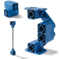
Equipped with ROSTA double rockers
AD-P, AD-C
and/or made out of
AR
elements
–
Ideal compensation when m
1
= m
2
–
Element selection analogue chapter 1, but with load of the two masses:
Actuated mass (+ material coupling of feeding mass)
m
1
[kg]
Driven mass (+ material coupling of feeding mass)
m
2
[kg]
Total oscillating mass
m =
m
1
+
m
2
[kg]
Dynamic spring value c
d
per double rocker
[N/mm]
– Calculation of c
t
and F based on the total mass (m
1
and m
2
)
–
Power input from eccentric drive with
ST
arbitrary
on m
1
or m
2
at
any point
alongside
m
1
or m
2
–
On demand, special double rocker arms with varying center distances A are available
as “customized rockers”
Size
(e.g. AU
15
)
max. load capacity per rocker [N]
max. revolutions n
s
[min
-1
]
*
K < 2
K = 2
K = 3
K = 4
α
+
5°
α
+
6°
15
100
75
60
50
640
480
18
200
150
120
100
600
450
27
400
300
240
200
560
420
38
800
600
500
400
530
390
45
1’600
1’200
1’000
800
500
360
50
2’500
1’800
1’500
1’200
470
340
60
5’000
3’600
3’000
2’400
440
320
Please contact ROSTA for the permissible load indications by higher accelerations
and for rocker elements offering higher load capacities. Usually are the revolutions
n
s
between 300 to 600 min
-1
and the oscillation angles max. ±6°.
* basics: “permissible frequencies” in the Technology part of the ROSTA catalogue.
The angle of oscillation
α
of each oscillat-
ing component (rockers accumulators and
drive head) has to be settled within the
permissible range (n
s
and
α
).
Calculation oscillation angle for rockers
Eccentric radius R [mm]
Center distance A [mm]
Oscillation angle
α
± [°]
α
=
arctan
[°]
A
R
c
d
=
3 · Md
d
· 360 · 1000
2 · A
2
·
π


