5.8
Motorbases
Motorbases
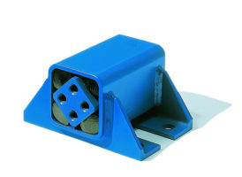
Type MB 50
1 Motor plate galvanized
2 Side supports galvanized
3 Pretensioning device galvanized
(MB 50
×
270-1 and MB 50
×
270-2: 1 device /
MB 50
×
400 and MB 50
×
500: 2 devices)
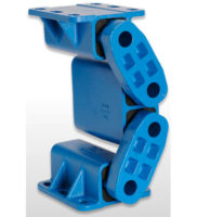
4
Rubber suspension element with cardanic bushings and
brackets blue painted (depending on size = 3–5 brackets)
5 Centre bolt retaining
collar. If required, the main centre bolt and retaining
collar can be switched to the opposite side. First block the underside of the
rubber suspension element (4). Remove the centre bolt and retaining collar.
Re-install the centre bolt and retaining collar from the opposite side. Remove
the blocking. The motorbase is now ready to install.
*
All ROSTA Motorbases MB 50 will be supplied with
motor plate installed in
“off-set”
configuration. Accord-
ing to the final positioning of the base, the operating
angle of the belts and the required tensioning travel, the
motor plate can be altered in
“centered”
position on
top of the element axis. Relevant threaded fixation holes
are existent in plate.
For possibly required higher
inclination of the motorplate,
the rotary plate(s) can be
removed and remounted
45° rotated.
1
2
4
3
5
Art. No.
Type
IEC
NEMA
AB
BB
C
D
E
Weight
(kg)
Motor Frame
Size
A
B
K
Motor Frame
Size
A
B
K
02 200 526
MB 50 × 270-1
160M
160L
254
254
210
254
14
14
254T
256T
254
254
210
254
14
14
320
315
245
463
25
44
02 200 527
MB 50 × 270-2
180M
180L
279
279
241
279
14
14
284T
286T
279
279
241
279
14
14
350
335
245
463
72
46
02 200 528
MB 50 × 400
200L
318
305
18
324T
326T
318
318
267
305
18
18
405
390
345
563
55
58
02 200 529
MB 50 × 500
225S
225M
356
356
286
311
18
18
364T
365T
356
356
286
311
18
18
465
420
425
643
72
64
Details regarding special designs, see pages 5.14 – 5.15.
Design
ATEX
with specific Art. No., example MB50 × 270-1: 02
3
00526. Details ATEX on page 5.4.
new
new
new
new


