5.10
Motorbases
Motorbases
Type MB 70
1
2
3
4
*
1 Motor plate
2 Side supports
3 Pretensioning devices = 2 devices
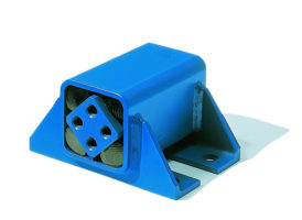
4 Rubber suspension element with
cardanic bushings
Art. No.
Type
IEC
NEMA
Weight
[kg]
Motor
Frame Size
A
B
K
Motor
Frame Size
A
B
K
AB
BB
C
D
E
02 200 710
MB 70 × 400
250M
406
349
22
404T
406
311
22
510
410
513
643
50
142
02 200 711
MB 70 × 550
280S
457
368
22
405T
406
349
22
560
565
663
793
50
169
280M
457
419
22
444T
457
368
22
02 200 712
MB 70 × 650
315S
508
406
26
445T
457
419
22
630
660
763
893
70
191
02 200 713
MB 70 × 800
315M
508
457
28
447T
457
508
22
630
805
913
1043
70
216
315L
508
508
28
449T
457
635
22
Details regarding special designs, see pages 5.14 – 5. 15.
Design
ATEX
with specific Art. No., example MB70 × 400: 02
3
00710. Details ATEX on page 5.4.
We will be glad to calculate your specific system, please ask for our relevant questionnaire.
*
All ROSTA Motorbases MB 70 will be supplied with
motor plate installed in
“centered”
configuration on
top of the element axis. According to the final positioning
of the base, the operating angle of the belts and the re-
quired tensioning travel, the motor plate can be altered in
“off-set”
position. Relevant threaded fixation holes are
existent in plate.
For possibly required additional tensioning travel of the
motor plate, the fork head of the pretensioning device
can be set in one of the eleven hole positions of the fric-
tion plate (3).
265
365
20
K
Offset E
A
AB
54
50
550
650
22
C
D
52,5
B
BB
15
350
only MB70x800


