3.10
Anti-vibration Mounts
Anti-vibration Mounts
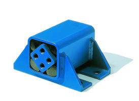
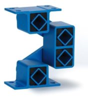
Type V
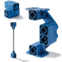
Further information to customized elements and installation examples as from page 3.14.
J
K
H
A
E
B
F
C
N
M
L
E
B
H
K
A
J
C
N
212
262
L
M
18x30
up to V 45
V 50
Art. No.
Type
Load
Gmin. – Gmax. [N]
on X- and Z-axis
A
B
C
E
øF
H
øJ
K
L
M
N
Weight
[kg]
05 011 001
V 15
300 –
800
49
80
51
55
9.5
3
20
10
40
M10
59
0.3
05 011 002
V 18
600 –
1'600
66
100
62
75
9.5
3.5
30
13
50
M10
74
0.7
05 011 003
V 27
1'300 –
3'000
84
130
73
100
11.5
4
40
14.5
60
M12
85
1.3
05 011 024
V 38
2'600 –
5'000
105
155
100
120
14
5
45
17.5
80
M16
117
2.7
05 011 005
V 45
4'500 –
8'000
127
190
122
140
18
6
60
22.5
100
M20
143
4.6
05 011 006
V 50
6'000
– 12'000
150
140
150
100
-
10
70
25
120
M20
193
7.5
Art. No.
Type
Natural frequency
Gmin. – Gmax.
[Hz]
Material structure
(zinc-plated screws)
05 011 001
V 15
30 – 23
Light metal profiles,
welded steel housings,
ROSTA blue painted
05 011 002
V 18
25 – 15
05 011 003
V 27
28 – 20
05 011 024
V 38
14 – 12
05 011 005
V 45
15 – 12
05 011 006
V 50
12 – 10
*
Alternativ mounting position 180° turned.
The max. load on
Y-axis
should not exceed
20 %
of the
X- resp. Z-axis capacity.
Momentary shock loads of 2.5 g in X- and Z-axis
admissible.
Applicable on tensile, pressure and shear load.
*
Z
X
Y


