
MOTOVARIO


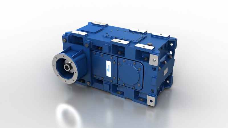


To install the gear reducer it is necessary to note the following recommendations:
Check the correct direction of rotation of the gear reducer output shaft before fitting the unit to the
machine.
In the case of particularly lengthy periods of storage (4/6 months), if the oil seal is not immersed in the
lubricant inside the unit, it is recommended to change it since the rubber could stick to the shaft or may
even have lost the elasticity it needs to function properly.
Whenever possible, protect the gear reducer against solar radiation and bad weather.
Ensure the motor cools correctly by ensuring good passage of air from the fan side.
In the case of ambient temperatures < -5°C or > +40°C call the Technical Service.
The various parts (pulleys, gear wheels, couplings, shafts, etc.) must be mounted on the solid or hollow
shafts using special threaded holes or other systems that anyhow ensure correct operation without
risking damage to the bearings or external parts of the units. Lubricate the surfaces in contact to avoid
seizure or oxidation.
Painting must definitely not go over rubber parts and the holes on the breather plugs, if any.
For units equipped with oil plugs, replace the closed plug used for shipping with the special breather plug.
Check the correct level of the lubricant through the indicator, if there is one.
Starting must take place gradually, without immediately applying the maximum load.
When there are parts, objects or materials under the motor drive that can be damaged by even limited
spillage of oil, special protection should be fitted.
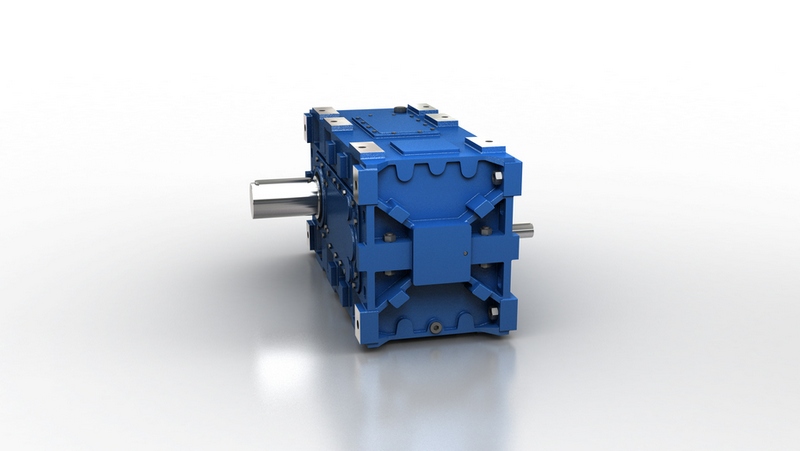
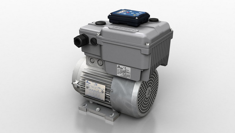
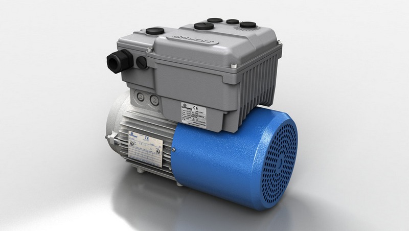
Assembling motor on pam flange
When the unit is supplied without motor, it is necessary to follow these recommendation to ensure the correct
assembly of the electric motor. Check that the tolerances for the motor shaft and flange correspond to the
“standard”. Carefully clean the shaft, spigot and surfaces of the flange removing traces of paint and dirt, and
confirm the key is fitted correctly. Fit the half coupling/sleeve to the motor shaft (see picture) taking care to
ensure the motor shaft and bearings are not damaged by avoiding excessive force and where necessary
using assembly equipment. Place the couplings elastic element onto the motor half coupling and position the
motor up to the gear unit ensuring the coupling element is aligned with the driven half coupling. Complete the
assembly using the fixing bolts.
Key-ways with tightened tolerances.
In case of Atex units, fit gasket (to be requested to MOTOVARIO SpA) between PAM flange and motor.
Flexible joint PAM Sleeve
S Series
/
ATEX
/
IEC
TECHNICAL CATALOGUE
1.5 INSTALLATION
11