
MOTOVARIO


11
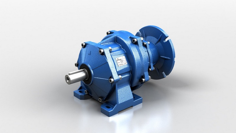
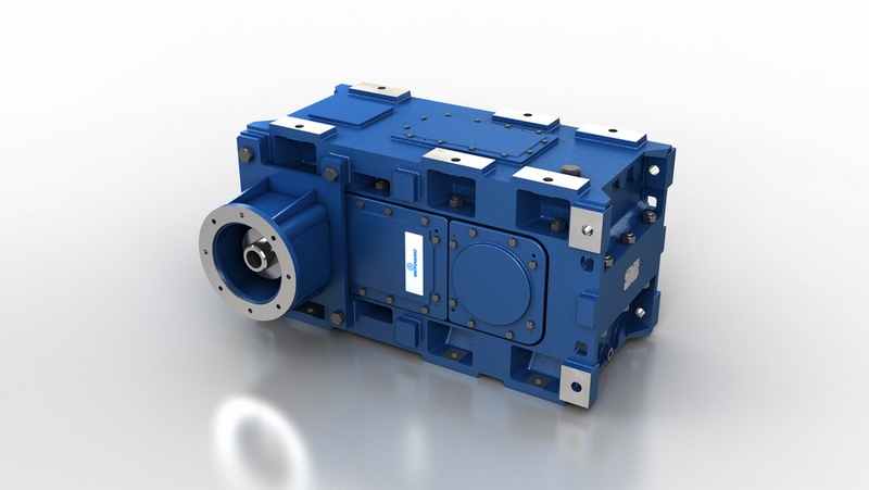
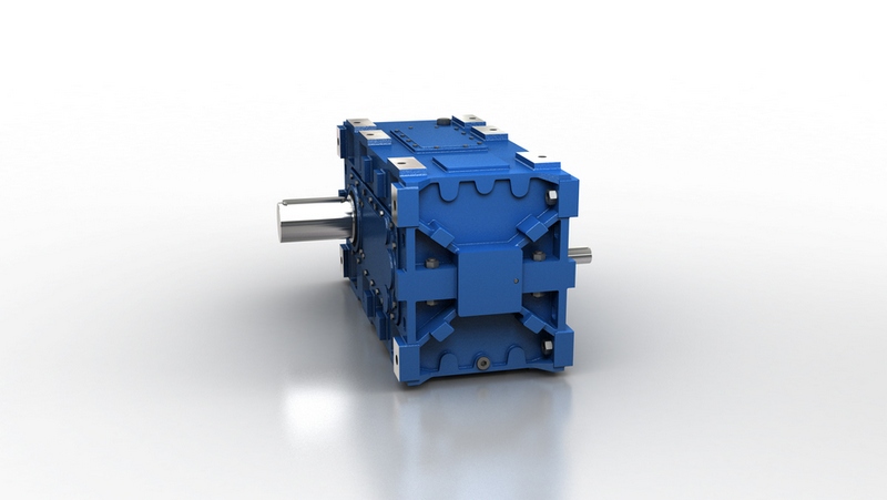
PARALLEL HELICAL AND BEVEL HELICAL
GEARBOXES
6
METHOD OF SELECTION
1) Calculate the required transmission ratio
i = n
1
/ n
2
2) Calculate the available torque at low speed shaft
M
2
= P
1
* 9550 *
/ n
2
[Nm]
3) Define the minimum service factor fs required by the application based on:
• Classification of load (uniform, moderate, heavy)
• Daily working hours [h/d]
• Number of starts / hour [starts / hour]
• Type of installed motor
See tables 1, 2 ,3 e 4.
4) Define the minimum reducer performance
M
N2
= M₂ * fs [Nm]
5) Select the reducer size, train of gears and transmission ratio based on M
N2
, n₂ and n
1
Verifications
a) Verify the thermal power. See tables 5, 6 and 7.
b) When there are overloads due to starting on full power, breaking, high inertia loads,
check the overload torque
(M
2max
) M
2max
≤
1,8 * M
N2
Note: overloads are instantaneous peaks (maximum acceptable duration 10 seconds)
c) For radial and / or axial loads on high and low speed shaft, contact technical service.
d) For input speed n
1
≥
1750 min
-1
contact technical
service:
Service factor
The minimum service factor required by the application is defined as
fs = fa * fb * fc