
MOTOVARIO


Information
4
Information
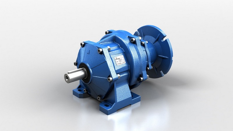
Helical geared motors
Product selection guide
For correctly selecting a gear reducer or geared motor, several essential pieces of data
are required:
A -
The rotational input speed to the gear reducer (
n1
) and the rotational output speed
(
n2
).
Through these two values it is possible to calculate the reduction ratio (
i
) of the gear
reducer using the following formula:
B -
The torque required by the application (
Mr2
).
The geared motor or gear reducer can be selected once this data is known.
This guide helps you to select the right product in just a few steps:
Geared motor selection
This guide indicates a brief sequence of steps for selecting a suitable product:
1
Determine the application’s actual service factor (
s.f.
). This parameter depends on the
type of load of the powered machine, the number of starts per hour and the hours of
operation (refer to the “Service factor” paragraph on page 5)
2
Calculate the input power
Pr1
using the required torque value
Mr2
, the speed
n2
and
dynamic efficiency value.
The dynamic efficiency value depends on the type of gear reducer and on the number
of gear reduction stages. (To calculate the efficiency value see page 3).
3
Consult the geared motor performance tables and identify a normalised power value
Pn1
exceeding the required power
Pr1
, such that:
4
Once the suitable nominal power has been identified, select the geared motor capable
of generating the rotational speed closest to the desired n2 value and with service
factor s.f. greater or equal to that required by the application.
In the geared motor selection tables the combinations include, 4-pole motors powered at
60Hz.
Gear reducer selection
1
Determine the application’s service factor (
s.f.
) (consult to the “Service factor” para-
graph on page 5) .
2
Calculate the reduction ratio i from the requested output speed
n2
and from the input
speed
n1
.
3
Calculate the torque
Mc2
for selecting the gear reducer through the torque required by
the application
Mr2
and the service factor s.f.:
4
Consult the Gear Reducer Performance tables looking for the reducer that, with the
reduction ratio closer to the calculated one, has a nominal torque
M2
so that:
Checks
Once the gear reducer or geared motor has been selected, the following checks should
be performed:
A -
Thermal power
The gear reducer’s thermal power must be equal to or greater than the installed me-
chanical power, or the power required by the application according to the indications
contained in the section (refer to the “Thermal power” paragraph on page 7).
B -
Maximum torque
Generally, the maximum torque (peak instantaneous load) that can be applied to the
gear reducer must not exceed 200% of the nominal torque M2.
C -
Radial loads
1
Verify that the radial loads acting on the input and/or output shafts are within with the
values indicated in the catalogue. If they exceed these values, increase the size of
the gear reducer or modify the external load capacity.
During the checking phase, it is important to remember that the values indicated in
the catalogue refer to loads acting on the mid-point of the shaft protrusion, therefore,
if the load is applied to a different position, appropriate formulas must be used to
calculate the admissible load in the desired position (refer to the “Radial loads”
paragraph on page 10).
2
If accessory output shafts are present, make sure that the applied load is compatible
with shaft size. If help is needed: contact MOTOVARIO TECHNICAL SERVICE.
D - If an electric motor is going to be fitted to the selected gear reducer, check for its appli-
cability by referring to the configuration table (see paragraph “Configurations” page 15).
M2
Mc2