FREUDENBERG SIMRIT

Technical Principles | Informations Techniques
Informaciones Técnicas | Princípios técnicos
32
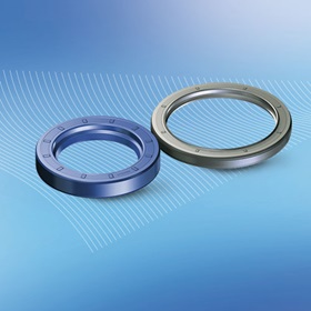
Installation of Simmerring Combi Seal
Bore requirements for all COMB±s which has not elastomer on
the outer diameter (ex. SF5 and SF6)
Tolerance:
ISO H8
Chamfer:
20° ± 5° x 1,5 mm (0.06 in)
Roughness:
R
a
= 0,8 … 3,2 µm
R
z
= 6,3 … 16 µm
R
max
< 16 µm
Shaft requirements
A
The requirements for Standard Simmerring are valid
A
Shaft hardening required.
Handling
A
Proceed carefully and ensure that the sealing lips are not
damaged during handling and when inserting the shaft
(this applies especially to spline shafts).
Bore requirements for all COMB±s which has elastomer on the
outer diameter (ex. SF19 and SF8)
Tolerance:
ISO H8
Chamfer:
20° ± 5° x 1,5 mm (0.06 in)
Roughness:
R
a
= 1,6 … 6,3 µm
R
z
= 10 … 25 µm
R
max
< 25 µm
Fitting procedure
A
The same installation instructions as for Standard
Simmerring are valid
A
Use care when inserting the shaft so that the polyurethane
lip does not bend
A
Please inquire for removal instructions (air side first).
Replacement
A
If a Simmerring Combi Seal is replaced, the shaft must be
replaced/renewed to fulfil the roughness, hardness and
tolerance requirements
A
For Standard Simmerring Combi Seal SF5 and SF6, a
sealant on the outside diameter is required.
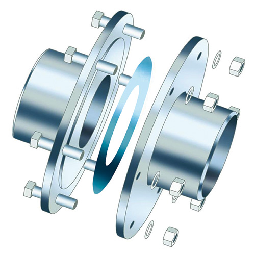
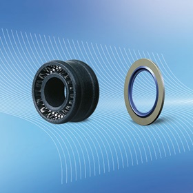
Installation of Simmerring Cassette Seal
Requirements for shaft and bore
Tolerance:
ISO H8/h8
Bore chamfer:
20° ± 5° x 1 mm (0.04 in)
Shaft chamfer:
20° ± 5° x 3 mm (0.12 in)
Roughness:
R
a
= 0,8 … 3,2 µm
R
z
= 10 … 16 µm
R
max
of the bore < 16 µm
R
max
of the shaft < 25 µm
Handling
A
The spring may not be removed
A
Do not attempt to open the seal
A
Store the seals stacked.
Types of installation (
→
Fig. 16)
A
Installation Case A
→
Fig. 17
A
Installation Case B
→
Fig. 18
A
Installation Case C
→
Fig. 19
A
Installation Case D
→
Fig. 20
A
Installation Case E
→
Fig. 21
Original installation
Installation in case of repair
Fig. 15
±nstallation during repair and unit assembly / Montage en cas de
réparation ou de remise en état du dispositif / Montaje al reparar y montar
el grupo / Montagem de reparo e unidade de montagem
Fig. 14
±nstalling a Simmerring with sealing lip made of PTFE / Montage
d'une bague Simmerring avec lèvre d'étanchéité en PTFE / Montaje de un
retén Simmerring con labio de sellado de PTFE / Montagem de retentor
Simmerring com lábio de vedação em PTFE