COMINTEC


68
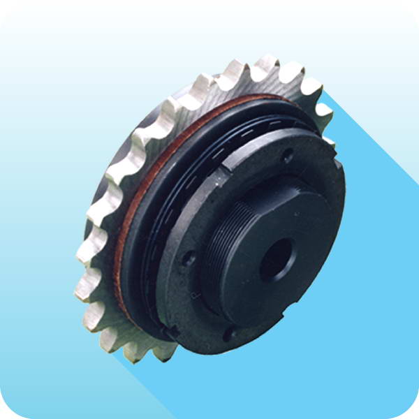
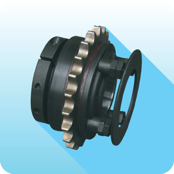
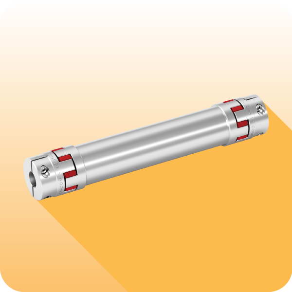
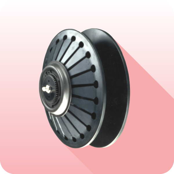
... + GEC - model with compact elas
Ɵ
c coupling: technical data
Size
Torque
[Nm]
A3
D3
E3 H7
M3
N3
U3
V3
Q3
D H7
F
R
U3
V3
DSR/F/AP
GEC
Nom
Max
pilot bore
max
max
0.56
0
70
110
78
50
10
28
63,5
32
10
M5
28
18
56
142
10
M5
1.90
1
280
420
108
70
12
38
89
49
12
M6
44
25
90
189
12
M6
2.110
2
570
860
130
80
15
45
111
65
15
M8
59
38
110
228
15
M8
3.130
3
980
1500
161
100
15
60
140
85
15
M8
77
45
130
268
15
M8
4.160
4
2340
3600
206
120
20
70
168
105
20
M10
97
55
160
323
20
M10
5.194
5
3880
5800
239
135
30
80
201
130
20
M10
120
65
215
360
20
M10
6.240 CB
6
15000
20000
6.240 CA
7.280 CB
7
30000
35000
7.280 CA
TECHNICAL DETAILS
DIMENSIONS
Size
Misalignments
Max speed
[Rpm]
Weight
[Kg]
DSR/F/AP
GEC
Angular
α
[ ° ]
Axial X
[mm]
Radial K
[mm]
con
Ɵ
nuous
intermi
Ʃ
ent
con
Ɵ
nuous
intermi
Ʃ
ent
con
Ɵ
nuous
intermi
Ʃ
ent
0.56
0
1°
1° 30’
± 0,7
± 1,5
0,5
0,7
5500
1,1
1.90
1
0° 48’
1°
± 0,7
± 1,5
0,5
0,7
5000
3,3
2.110
2
0° 36’
0° 48’
± 0,7
± 1,5
0,6
0,7
4500
5,9
3.130
3
0° 30’
0° 42’
± 0,8
± 1,6
0,6
0,8
4000
10,9
4.160
4
0° 24’
0° 30’
± 0,8
± 1,6
0,6
0,8
3100
19,8
5.194
5
0° 24’
0° 30’
± 0,8
± 1,6
0,6
0,8
2800
30,5
6.240
6
0° 24’
0° 30’
± 0,8
± 1,6
0,6
0,8
-
-
7.280
7
0° 24’
0° 30’
± 0,8
± 1,6
0,6
0,8
-
-
NOTES
• These details refer only for the coupling (GEC); for connec
Ɵ
on details see on page 67.
• Weights are relevant only to the pilot bore (GEC).
• Microswitches EM1 or EM2 and induc
Ɵ
ve sensor PRX see page 73
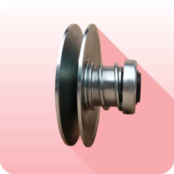
OTHER COUPLING MODELS ON REQUEST
Model
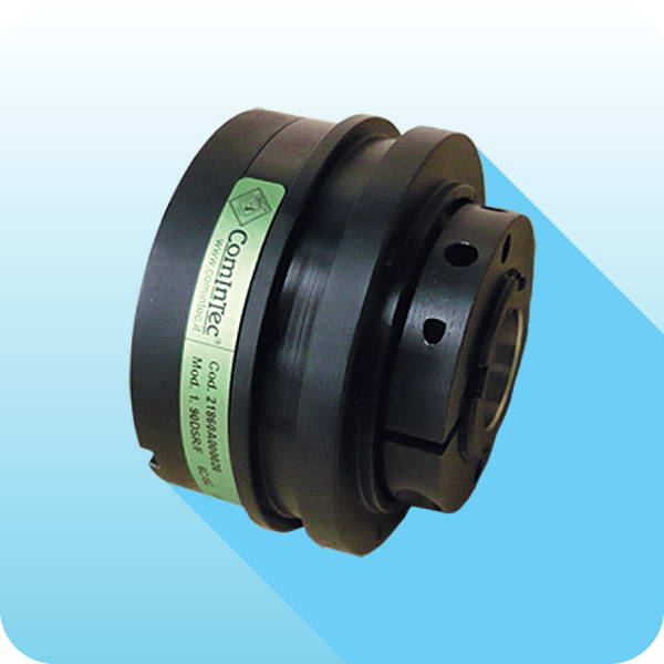
DSR/F/AP
with single
fl
exing disc coupling
GTR-S
,
for applica
Ɵ
ons where torsional rigidity is required and without
the ability to accommodate radial misalignment.
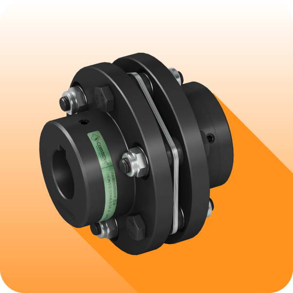
Model
DSR/F/AP
with double
fl
exing torsionally rigid metal disc
coupling
GTR-D
, when torsional rigidity is required and
ability to accommodate radial misalignment.
On request