48
GF -
fl
exible coupling: technical data
Made in steel fully turned with standard treatment of phospha
Ɵ
ng.
Simple manufacturing.
High angular misalignments possible.
Elas
Ɵ
c element with an internal nylon weave for high reliability.
Possible to maintain without the need to move the hubs.
Finished bore (in ISO H7 tolerance) with keyway (in ISO H9 tolerance), and low roughness.
ON REQUEST
Various hub connec
Ɵ
on type available.
Speci
fi
c surface treatments.
Customized versions for speci
fi
c needs.
Connec
Ɵ
on to the Torque limiter's (safety coupling) range possible.
DIMENSIONS
On request
TECHNICAL CHARACTERISTICS
NOTES
• The weights refer to the coupling with minimum bore.
• Iner
Ɵ
as refer to the coupling with maximum bore.
•
For choice and availability of di
ff
erent hub connec
Ɵ
on type see pages 4 and 5.
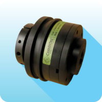
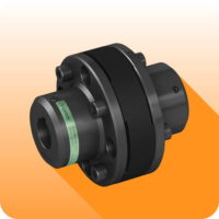
The GF coupling, even if being built simply, assures a high elas
Ɵ
c reliability which allows the recovery of high angular misalignments
(up to 5°), absolutely reducing the drive irregulari
Ɵ
es.
It is composed of two hubs in steel UNI EN10083/98 fully turned and by an elastomeric central ring connected with screws and bolts in
alternate way in respect to the two hubs.
For pre-selec
Ɵ
on of the coupling's size you can use the generic formula indicated on page 6.
Model
GF
fl
exible coupling
Locking type
see hub connec
Ɵ
on type list at page 4
Size
From X0 to X5
ORDER EXAMPLE
FLEXIBLE COUPLING
Model
Size
Bore 1
Locking type
bore 1
Bore 2
Locking type
bore 2
GF
Size X3
bore Ø35 H7
A1
bore Ø45 H7
A1
Size
A
B
C
D
E H7
N
P
Q
R
U
V
pilot
max
X 0
98
100
78
48
10
28
45
17
34
107
8
M4
X 1
128
130
100
70
14
38
55
24
44
134
12
M6
X 2
162
165
125
90
19
48
72
29
56
173
12
M6
X 3
178
185
140
105
19
55
76
36
60
188
15
M8
X 4
198
205
160
125
28
65
84
44
68
212
15
M8
X 5
235
240
195
155
30
85
100
50
80
250
15
M8
Size
Torque
[Nm]
Weight
[Kg]
Iner
Ɵ
a
[Kgm
2
]
Max speed
[Rpm]
Misalignments
Elas
Ɵ
c element
angular
α
[ ° ]
axial
X
[mm]
radial
K
[mm]
Hardness
[Sh-A]
Opera
Ɵ
ng
temperature
[°C]
Maximum
temperature
[°C]
Nom
Max
X 0
75
225
3,4
0,00256
5000
3°
1,5
1
70 ± 5
-25 ÷ +70
+130
X 1
230
690
6,0
0,00826
4500
4°
2
1
X 2
470
1410
8,2
0,02654
3600
4°
2,5
1,5
X 3
750
2250
12,7
0,04268
3500
4°
3
1,5
X 4
1125
3375
16,9
0,07775
2800
4°
3
1,5
60 ± 5
X 5
1700
5100
22,2
0,19375
2500
4°
3,5
1,5


