40
C
nom
> C
mot
•
f
•
K
• f
T
• f
A
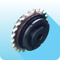
GEC - compact elas
Ɵ
c coupling: introduc
Ɵ
on
Made in steel fully turned with standard treatment of phospha
Ɵ
ng.
Maintenance without removing the coupling
Suitable for working in high temperatures.
Sta
Ɵ
cally balanced, suitable to absorb vibra
Ɵ
ons.
Highest protec
Ɵ
on.
Excellent value torque/dimensions.
ON REQUEST
Various hub connec
Ɵ
on type available.
Speci
fi
c treatments or aluminum version fully turned available.
Customized versions for speci
fi
c needs including hub/
fl
ange connec
Ɵ
on.
Connec
Ɵ
on to the Torque limiter's (safety coupling) range possible.
DESCRIPTION OF THE ELASTOMERIC ELEMENT
DIMENSIONING
FITTING
Shock factor (K)
1,2
= light shock
1,5 = medium shock
1,8 = hard shock
Thermic factor (f
T
)
1
= -36 ÷ +60 °C
1,2 = 80 °C
1,4 = 100 °C
1,8 = 120 °C
Star
Ɵ
ng frequency factor (f
A
)
1
= 0 ÷ 120 star
Ɵ
ng each hour
1,2 = 240 star
Ɵ
ng each hour
1,4 = 400 star
Ɵ
ng each hour
1,6 = 800 star
Ɵ
ng each hour
1,8 = 1600 star
Ɵ
ng each hour
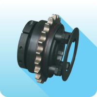
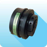
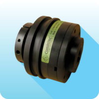
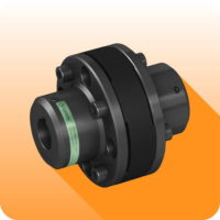
The GEC coupling is composed of two hubs in steel UNI EN10083/98 fully turned. These two hubs are connected by radial pins, made in steel
with high resistanceand seated within the elastomeric elements.
These pins, with their relevant elastomeric elements, are protected by an external band, allowing the coupling a high grade of protec
Ɵ
on.
This construc
Ɵ
on feature allows the user to be able to perform maintenance, by subs
Ɵ
tu
Ɵ
ng the elas
Ɵ
c elements, without the need to move
the two transmission hubs/sha
Ō
s, reducing maintenance
Ɵ
mes and op
Ɵ
mizing the plant produc
Ɵ
vity.
Par
Ɵ
cularly suitable for connec
Ɵ
ng Pelton turbines, for the coupling between engines and worm compressors and in general for transmission
where safety is highly necessary without compromising the quality and e
ff
ec
Ɵ
veness of the same transmission.
Having completed and checked the coupling's choice, in accordance to the torque to be transmi
Ʃ
ed, it is necessary now, to take into
considera
Ɵ
on, the necessary
fl
exibility comparing the misalignments allowed from the kind of coupling selected, with the real ones, seen by
the sha
Ō
s to be connected. It is important to consider that misalignments, axial, angular and parallel, must be considered paired together, as
inversely propor
Ɵ
onal (one reduces when the other increases). If all types of misalignments occur, it is necessary that the sum in percentage
respect to the maximum value doesn't exceed 100%.
The main features that dis
Ɵ
nguish this elas
Ɵ
c element are as follows:
•
Good resistance to all common lubricants and hydraulic
fl
uids.
•
Op
Ɵ
mum mechanical proper
Ɵ
es.
•
Green element suitable to operate for short periods up to 170 °C.
For pre-selec
Ɵ
on of the coupling's size you can use the generic formula indicated on page 6. Alterna
Ɵ
vely it is possible to determine the
coupling's nominal torque using several correc
Ɵ
on factors:
Speci
fi
c procedures to assemble this coupling are not required.
1)
Achieve radial and axial alignment as precisely as possible for maximum absorp
Ɵ
on of possible misalignments and the long life of the
coupling.
2)
Having pre-assembled the coupling, insert the external half-hub on one sha
Ō
. Check that the external parts of the two sha
Ō
s don't exceed
the relevant half-hub's surface (quote “N”) and
fi
x this one to the sha
Ō
with its relevant
fi
xing system.
3)
Close the second sha
Ō
inser
Ɵ
ng it into the internal half-hub for a quan
Ɵ
ty not higher than the length of the bore (quote “N”). If the
inser
Ɵ
on should be di
ffi
cult, due to an accentuated misalignment, it is advisable to release all the connec
Ɵ
on pins, this will allow for a
higher
fl
exibility between the two half-hubs.
4)
A
Ō
er having inserted and
fi
xed the hubs, take away each connec
Ɵ
on pin, damp them with loc
Ɵ
te threadlocker, and reassemble and
Ɵ
ghten them carefully in progressive way following a cross sequence.
5)
Cover the pins with the protec
Ɵ
on band, making the holes of the band coincide with the relevant locking spheres.
Where:
C
nom
= theore
Ɵ
c nominal torque of the coupling
[Nm]
C
mot
= nominal torque motor side
[Nm]
f
= service factor
(see page 5)
f
A
= star
Ɵ
ng frequency factor
[Hz]
f
T
= thermic factor
K
= shock factor


