12
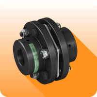
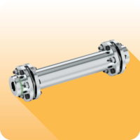
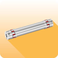
GTR/DBSE - torsionally rigid coupling with spacer: introduc
Ɵ
on
Made in steel and fully turned.
Galvanizing corrosion proo
fi
ng.
Disk pack in stainless steel.
Maintenance and wear free.
Personalized spacer version for a speci
fi
c D.B.SE.
Welded spacer for high torsional rigidity.
ON REQUEST
Use in applica
Ɵ
ons with high opera
Ɵ
on temperatures (> 150 °C) possible.
Dynamic balancing up to Q=2,5 possible.
Customized versions for speci
fi
c needs.
Di
ff
erent hub connec
Ɵ
on type possible (pages 4 and 5).
APPLICATION EXAMPLE
In the case of DBSE> 3 m with high speed, it is necessary to use an intermediate sha
Ō
with support and bearing
DESCRIPTION OF DISCS
The fundamental elements of this torsionally rigid coupling are the disc packs, built from a series of stainless steel discs type AISI 304-C,
connected by steel bushes. This disc pack is connected in an alternate way to the hub
fl
ange or the eventual spacer, by using screws in steel
class 10.9 and the relevant self-locking nuts.
With reference to the con
fi
gura
Ɵ
on, the disc packs can be:
A)
Con
Ɵ
nuous ring disc pack for 6 screws (coupling sizes 1-7)
B)
Sec
Ɵ
onal disc pack for 6 screws (coupling sizes 8-11)
C)
Sec
Ɵ
onal disc pack for 8 screws (coupling sizes 12-15)
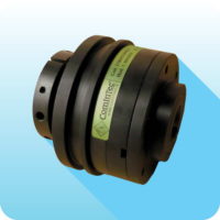
This backlash free coupling with spacer , called the GTR/DBSE (Distance Between Sha
Ō
Ends), consists o
ff
a central spacer that is made to
order depending on the applica
Ɵ
on and two
fl
exible disc packs and hubs allowing for the connec
Ɵ
on of two driver sha
Ō
s located apart.
This type of disc coupling is made of special steel with the disc packs manufactured in AISI 304 stainless steel, in order to obtain a wear and
maintenance free
fl
exible coupling. To promote a long life even in adverse condi
Ɵ
ons the coupling is supplied with an an
Ɵ
-corrosive surface
treatment. All the parts of the coupling (with excep
Ɵ
on of the DBSE spacer version) are sta
Ɵ
cally balanced in class DIN-ISO 1940:1:2003 Q 6.3
before machining of the key and its locking screw.
In accordance with the speci
fi
c requirements of the applica
Ɵ
on, you can perform a sta
Ɵ
c or dynamic balancing di
ff
erent on each separate
component or the coupling fully assembled.
Connec
Ɵ
ng two driving units situated some distance apart.


